Table of Contents
Logic Gates:
Logic gates are the building blocks of digital computers. A logic gate is an electronic circuit (or device) with two or more inputs but one output which occurs only for certain combinations of inputs.
There are three basic gates, viz., OR, AND and NOT. Each logic gate is characterized either by an input/output table known as the truth table or by a certain equation known as the Boolean equation.
Truth Table- It is a table that shows the input/output possibilities of a given logic gate.
Boolean Equation- Since binary algebra deals with 0 and 1 only, simple logic can be expressed through certain mathematical operations based on binary algebra and the equations so written are known as Boolean equations.
OR Gate:
An OR gate is a device that has any number of input terminals more than one but with a single output terminal. For simplicity, we prefer to deal with a two input OR gate here.
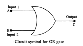
An OR gate gives an output pulse when input is present in at least one input terminal. The circuit symbol for a two input OR gate is shown in the figure below.
Truth Table or Character Table for OR Logic:
| Input A | Input B | Output C |
|---|---|---|
| 0 | 0 | 0 |
| 1 | 0 | 1 |
| 0 | 1 | 1 |
| 1 | 1 | 1 |
It may be seen in the character table that the output is 1 when input A is 1 OR input B is OR both A and B are one each. The output is zero only when all inputs are zero.
The Boolean algebra notation for OR logic is-
| A + B = C |
As we know 0 + 0 = 0, 1 + 0 = 1, 0 + 1 = 1. However for 1 + 1 we may not write 2 (as 2 is not included in binary algebra notaions), but we say that the corresponding value is high so we may write 1 + 1 = 1 for the present purpose.
A simple switching circuit for OR operation is shown in figure (a). With both switches S1 and S2 open (i.e., A = 0, B = 0) current will not flow through bulb which will not glow (C = 0). With any one of the switch closed (A = 1 or B = 1) or with both switches closed (A = 1 and B =1) the bulb will glow (C = 1). Thus, the character table is satisfied.
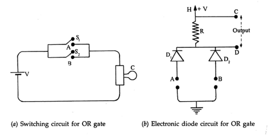
The electronic diode circuit is shown in figure (b). Both diodes are initially reverse biased through resistor R by a battery of emf V between points H and ground. The output is taken across the resistance R. With A = 0, B = 0, both diodes are reversed biased, no current flows through R, hence the potential difference is Zero across R i.e., C = 0. With a large positive pulse at input A, diode D1 is forward biased, the path for current opens through D1 and a potential difference is obtained across R hence we get C =1. Since D1 provides almost zero resistance, point D of the output is effectively at ground potential. The same thing happens if a large positive pulse is given at input B (i.e., B = 1) or at both inputs A and B simultaneously (i.e., A = 1 and B = 1). Thus, the truth table is satisfied.
AND Gate:
The AND gate is a device that has two or more inputs and one output. In Boolean Algebra, A.B = X, implies that X equals A and B.
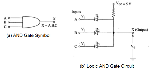
The AND gate is a logic gate that gives an output of 1 only when all of its inputs are 1. Thus, its output will be 0 when at least one of its inputs is 0. Figure (b) shows a 3-input AND gate circuit using three diodes. The AND gate may be considered equivalent to a circuit in which a number of switches are connected in series. Only when all the switches are on, will there be an output.
Truth Table or Character Table for AND Logic:
| Input A | Input B | Input C | Output X |
|---|---|---|---|
| 0 | 0 | 0 | 0 |
| 0 | 0 | 1 | 0 |
| 0 | 1 | 0 | 0 |
| 1 | 0 | 0 | 0 |
| 1 | 0 | 0 | 0 |
| 1 | 1 | 0 | 0 |
| 1 | 1 | 1 | 1 |
As in Fig (b), when inputs A = B = C = 0, all the diodes will be forward biased and will conduct, the output will be zero.
When A = B = C = 1, all the diodes will be reverse biased and will remain off. The output will be high, i.e., equal to 1.
When any of the inputs is high, the corresponding diode will conduct, and thus the output will be zero. As shown in truth table, X = 1 only when A = B =C = 1.
NOT Gate:
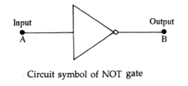
A NOT gate is an electronic circuit (or device) in which output is not present when input is present i.e. its output is zero if the input is 1 and output is 1 if the input is zero. In Boolean Algebra, Ā = B indicates that B equals NOT A.
Truth Table or Character Table for NOT Logic:
| Input A | Output B |
|---|---|
| 0 | 1 |
| 1 | 0 |




Comments (No)