Table of Contents
What is Potentiometer?
As the name suggests a potentiometer is a device that can measure electric potential at any given point or the potential difference between any two given points in an electrical circuit.
Potentiometer Construction:

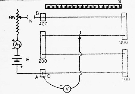
It consists of a long uniform wire of manganin or constantan fixed on a wooden board (sometimes, there are four or more wires, each one metre long, connected in series by thick copper strips). The ends of the wire are fixed to screws ‘A’ and ‘B’. A metre scale is fixed on the wooden board parallel to the length of the wire.
A battery E, Key K, Ammeter A1 and Rheostat Rh are connected between A and B. This circuit is called an auxiliary circuit. The positive end of the voltmeter is connected to end A whereas the negative end is connected to Jockey J which is free to move on the wire.
Potentiometer Working Principle:
Suppose A and ρ be the area of cross-section and specific resistance of the material of the wire respectively. Let V be the potential difference across the wire of length l and let R be the resistance of a wire of length l. Let I be the current flowing through the wire.
From Ohm’s Law,
| V = IR …………….(1) |
Also, we know,
| R = ρ x l/A …………(2) |
Put (2 ) in (1)-
| V = I x ρ x l/A = Kl (Where K = Iρ/A) |
If A and I are kept constant-
| V ∝ l |
Hence fall of potential across any point of the wire is directly proportional to the length of that portion of the wire, provided A and I are kept constant.
Applications of Potentiometer:
Comparision of EMF’s of Two Cells using Potentiometer:

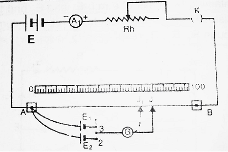
Take a potentiometer. Connect a battery E, Key K, ammeter A1 and Rheostat Rh, between A and B. This circuit is called an auxiliary circuit.
The positive terminals of the two cells E1 and E2 (whose emf’s are to be compared) are connected to point A of the potentiometer wire. Their negative terminals are connected to terminals (1) and (2) of the two-way key. The terminal (3) of the two-way key is connected to Jockey J through Galvanometer G. Put the key K so that the auxiliary circuit is completed and now with the help of rheostat, adjust a constant current in the potentiometer wire.
Connect terminals (1) and (3) of the two-way key. Due to this, cell E1 comes into the circuit. Due to this, galvanometer G gives deflection. Now, move the Jockey on the wire, a position J is reached, when the galvanometer shows zero deflection. Note AJ. Let AJ = l1. Then from the principle of potentiometer-
| E1 ∝ l1 ⇒ E1 = Kl1 ……………..(1) Where K is constant of proportionality |
Disconnect terminals (1) and (3) and connect terminals (2) and (3) of the two-way key. Due to this cell E2 comes into the circuit. Hence, galvanometer G gives deflection. Now move the Jockey on the wire, a position J’ is reached, when galvanometer shows zero deflection. Note AJ’. Let AJ’ = l2.
| Then E2 ∝ l2 ⇒ E2 = Kl2 ……………..(2) |
Divide (1) by (2), we have-
| E1/E2 = Kl1/Kl2 ⇒ E1/E2 = l1/l2 |
Internal Resistance of the Cell using Potentiometer:

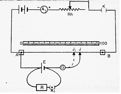
Take a potentiometer to connect a battery B, Key K, ammeter A1 and Rheostat Rh between A and B. This circuit is called an auxiliary circuit.
The positive terminal of cell E is connected to point A of the potentiometer wire, whereas the negative terminal is connected to Jockey J through galvanometer G. Also, a resistance box R and key K1 are connected between positive and negative terminals of the cell E. Press the key K, an auxiliary circuit is completed and now with the help of Rheostat, adjust a constant current through potentiometer wire.
Now move the Jockey on the wire, a position J is reached when the galvanometer gives zero deflection. Note AJ. Let AJ = l1. In this case, emf (E) of the cell is given by-
| E1 ∝ l1 ⇒ E1 = Kl1 ……………..(1) Where K is constant of proportionality |
Now, press the keys K and K1. Move the Jockey on the wire, a position J’ is reached, when galvanometer gives zero deflection. Note AJ’. Let AJ’ = l2. In this case, potential difference (V) between two poles of the cell is given by-
| V ∝ l2 ⇒ V = Kl2 ……………..(2) |
Divide (1) by (2), we have-
| E/V = Kl1/Kl2 ⇒ E/V = l1/l2 ……………..(3) |
We know internal resistance (r) of the cell of emf E is given by-
| r = (E/V – 1) R |
Put the value of E/V from (3), we have-
| r = (l1/l2 – 1) R |
Thus knowing l1, l2 and r, we can find the internal resistance of the cell.
Superiority of Potentiometer over Voltmeter:
A voltmeter can be used to measure or compare emf and potential differences. In such a case the deflection of the voltmeter needle is read. The accuracy of this reading depends upon the least count of the voltmeter. The least count of voltmeter of higher ranges is naturally large and hence the error in measurement is large. On the other hand, the potentiometer method is a null method in which we measure the length of wire, the least count of which is 1 mm. By using a very long potentiometer wire we may have a very small potential gradient. The measured voltage is found by multiplying the potential gradient (K) and balancing length (l). Thus the possibility of maximum error (small value of K multiplied by 1mm) is rather small. Hence, the potentiometer method is much more accurate than a voltmeter.
Secondly, as the null point in potentiometric measurement is attained, no current flows through the galvanometer, i.e., no current is derived out from the cell in the galvanometer circuit. This means that the actual open circuit emf of this cell is obtained. The situation becomes equal to an ideal voltmeter which is supposed to have an infinite resistance.


Comments (No)