Table of Contents
Applications of Interference:
The interference phenomenon is widely used in various fields. Some common applications are-
(1) Used for very accurate determination of the wavelength of light.
(2) Used for checking the planeness of a surface.
(3) Used for measuring small distances such as compression and elongation in metal rods or crystals. Thus ut can be used for finding linear expansion, Young’s modulus etc.
(4) Used for finding the thickness of small objects such as thin films.
(5) Used for determining ‘µ’ of liquids and gases.
(6) Used in the production of non-reflecting glasses.
Engineering Applications of Interference:
Following are the engineering applications of interference.
Testing of Optical Flatness:
The flatness of a given specimen surface is tested by placing a standard optically flat glass on that surface and the fringes formed are then viewed.

For Example- If the specimen surface is perfectly flat, then the thickness of air film enclosed between two surfaces is zero at all places and hence path difference between pairs of reflected beams will be equivalent to λ/2. Thus due to destructive interference, the entire surface will appear without any fringes. (fig. 1).
If the surface is not optically plane, the various types of fringe patterns are observed. (fig. 2 to 6).
Measurement of Mechanical Gauges (i.e. accurate measurement of dimensions):
The gauge measurement of blocks is used in workshops where very accurate standards of measurements of length are required. Here the theory of wedge film is applied.
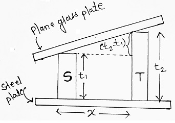
‘S’ is the block of standard length and ‘T’ is the block whose length is to be tested.
Both blocks are kept on an optically flat steel plate. An optically flat glass plate is kept on the top of two blocks.
If the length of the two blocks is not identical, the top glass plate rests as shown in fig. A wedge-shaped air film is formed between top glass and standard gauge. The interference fringes formed can be seen through a travelling microscope. The edge-to-edge distance between a standard block and test block is measured (x) and the number of fringes crossing can be counted.
According to wedge theory, the spacing between any two bright (or any two dark) fringes is λ/2µ.
If ‘m’ is the number of dark fringes spaced between t1 and t2 (having edge-to-edge distance x), then we can write-
| (t2 – t1) = mλ/2µ ……….(i) |
Let ‘n’ be the number of fringes per unit length, then we can write-
| n = m/x ⇒ m = nx ……….(ii) |
Therefore, equation (i) now takes the form as-
| (t2 – t1) = nxλ/2µ But µ = 1, for air, then- (t2 – t1) = nxλ/2 ……….(iii) Where t2 = height of test block. t1 = Height of standard block. n = number of fringes per unit length. x = edge to edge distance between S and T. λ = wavelength of light used. |
Non-reflecting Glass or Antireflection Thin Film Coatings:
Non-reflecting lenses or contact lenses are used in good cameras, binoculars and telescopes. When light is incident on the camera lens, some of the light is lost by a partial reflection and the image formed is less bright. Therefore, comparatively large exposure is needed to photograph the object. To avoid this, the lens surfaces are coated by a thin film of suitable material. The layer is transparent to light and has a refractive index intermediate between air and glass. The thickness of films is so chosen that the light reflected from two faces of coated layer produces destructive interference.
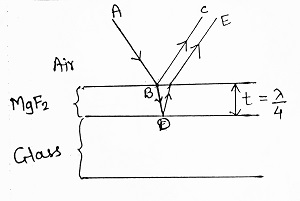
Let a thin film of MgF2 is deposited on glass. Light reflected from the bottom surface of the film (i.e. film-glass interface) has an extra path and it passes through the film twicely. For anti-reflection, the two interfering rays (i.e. BC and DE) should interfere destructively i.e. path difference = λ/2, but this path difference is equivalent to 2t i.e. for anti-reflection, 2t = λ/2 ⇒ t = λ/4.
Thus if a film is having thickness ‘λ/4’, then it is able to produce anti-reflection. In the same way, by satisfying the condition of constructive interference at reflected rays, the reflectivity of the surface can be increased.





Comments (No)