Radiation Detectors:
A hot body loses heat by the well-known processes of conduction and convection. When the loss of heat by these processes is prevented, even then a hot body is found to lose heat energy. We say that the hot body is radiating energy.
The thermal radiation so emitted can be detected by using instruments. Some of the instruments used for this purpose are described below:
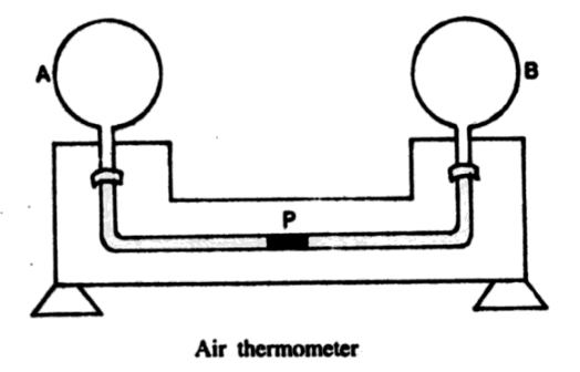
(1) Air Thermometer- Differential air thermometer consists of two bulbs A, and B connected through a glass tube bent twice at right angles. The tube has a small pellet of mercury, P. When the two bulbs are at the same temperature the pellet of mercury is in the middle, otherwise, it shifts towards one side.
(2) Bolometer- The fact that the resistance of a conductor changes with temperature has been utilized in the construction of a bolometer which measures the amount of radiation falling on it. It consists of very thin strips of platinum which are joined in the form of a grid. The strips are coated with a thin layer of lamp black so that they may absorb almost the whole of the radiant energy falling on them.
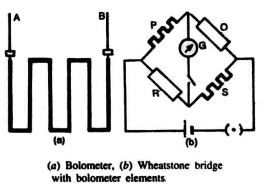
A lamp black coated platinum strip forms one element of a bolometer. It is connected to one of the arms of the Wheatstone Bridge and the bridge is balanced. When the bolometer strip is exposed to radiation, the temperature rises on account of the absorption of radiant energy. The bridge is, therefore, distributed and a deflection is produced in the galvanometer which is a measure of the amount of radiant energy falling on the element.
In order to increase the sensitivity a bolometer with two elements P and S is used to detect radiations. A detailed study of the Wheatstone bridge shows that if the two elements P and S are connected in the opposite arms of the bridge then an increase in resistance of P causes a deflection in the galvanometer which is in the same direction as that caused by the increase in S. The two elements P and S of the bolometer are mounted not-side-by-side but one is placed behind the other so that radiant energy passing through the open spaces of a grid of element P is caught by the element S.
(3) Thermopile- A thermopile is an arrangement of a large number of thermoelectric junctions joined in series and connected with a galvanometer to indicate the presence of radiations.
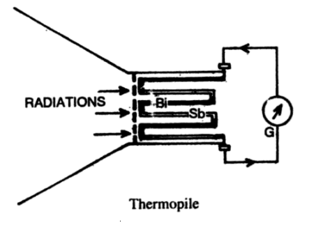
The thermoelectric junctions are arranged in the form of a cube such that all hot junctions A, A … lie in one face of the cube while all cold junctions B, B … lie in the opposite face. The face containing hot junctions is covered with a layer of lamp black.
When the radiations fall on the blackened face, it becomes hot and a thermo-electric current is set up which gives a measure of the radiant energy.
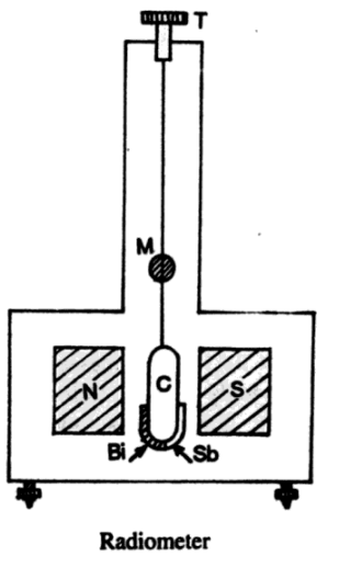
(4) Radiometer- It consists of a thermocouple of bismuth and antimony, joined with a copper coil, which is suspended in between the two poles of a horse-shoe magnet, in a manner like a galvanometer. When radiations fall on the junction, the thermoelectric current is produced and the coil is deflected. As the deflection of the coil is proportional to the intensity of incident radiations, a radiometer can be used to measure the intensity of the incident radiations.




Comments (No)